ASME B1.3 pdf download
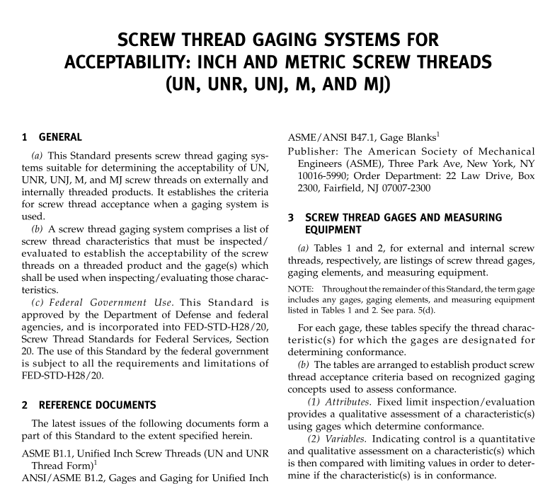
ASME B1.3 pdf download Screw Thread Gaging Systems for Acceptability: Inch and Metric Screw Threads (UN, UNR, UNJ, M, and MJ)
GENERAL
(a) This Standard presents screw thread gaging systems suitable for determining the acceptability of UNUNR,UNI M,and M screw threads on externally andinternally threaded products. It establishes the criteriafor screw thread acceptance when a gaging system isused.
(b) A screw thread gaging system comprises a list ofscrew thread characteristics that must be inspected/evaluated to establish the acceptability of the screwthreads on a threaded product and the gage(s) whichshall be used when inspecting/evaluating those charac-teristics.
(c) Federal Government Use. This Standard isapproved by the Department of Defense and federalagencies,and is incorporated into FED-STD-H28/20Screw Thread Standards for Federal Services, Section20 The use of this Standard by the federal governmentis subject to all the requirements and limitations ofFED-STD-H28/20.
2 REFERENCE DOCUMENTS
The latest issues of the following documents form apart of this Standard to the extent specified herein.ASME B1.1.Unified Inch Screw Threads(UN and UNRThread Form)ANSI/ASME B1.2, Gages and Gaging for Unified InchScrew ThreadsASME B1.7,Screw Threads: Nomenclature, Definitions.and Letter Symbols’
ASME B1.13M,Metric Screw Threads: M ProfileASME B1.15, nified Inch Screw Threads (UNJ Thread
Form)ANSI/ASME B1.16M, Gages and Gaging for Metric MScrew Threads
ASME B1.21M,Metric Screw Threads: M ProfilelANSI/ASME B1.22M, Gages and Gaging for M SeriesMetric Screw Threads’
ASME B46.1,Surface Texture (Surface RoughnessWaviness, and Lay)
ASME/ANSI B47.1,Gage BlanksPublisher: The American Society of MechanicalEngineers (ASME)Three Park Ave,New York,NY10016-5990: Order Department: 22 Law Drive,Box2300,Fairfield,NT 7007-2300
SCREW THREAD GAGES AND MEASURINGEQUIPMENT
(a) Tables 1 and 2, for external and internal screwthreads, respectively, are listings of screw thread gages,gaging elements, and measuring equipment.
NOTE: Throughout the remainder of this Standard, the term gageincludes any gages, gaging elements, and measuring equipmentlisted in Tables 1 and 2. See para, 5(d).
For each gage, these tables specify the thread charac-teristic(s) for which the gages are designated fordetermining conformance.
(b) The tables are arranged to establish product screwthread acceptance criteria based on recognized gagingconcepts used to assess conformance.(1) Attributes. Fixed limit inspection/evaluationprovides a qualitative assessment of a characteristic(s)using gages which determine conformance.
(2) Variables. Indicating control is a quantitativeand qualitative assessment on a characteristic(s) whichis then compared with limiting values in order to deter-mine if the characteristic(s) is in conformance.
4GAGING SYSTEMS
(a) Tables 3 and 4 present screw thread gaging systems for inspection/evaluation of externally and inter-nally threaded products, respectively.
(b) Three gaging systems for inspection/evaluationof threads on threaded products are established hereinto provide a choice depending on the engineeringrequirement of the threaded product. These are identi-fied as Systems 21, 22 and 23. The difference betweengaging systems is the level of inspection/evaluationdeemed necessary to satisfy that conformance has beenachieved.
(c) Since most screw thread applications do notrequire that all of the characteristics described in the
