ASME Y14.40.4 pdf download
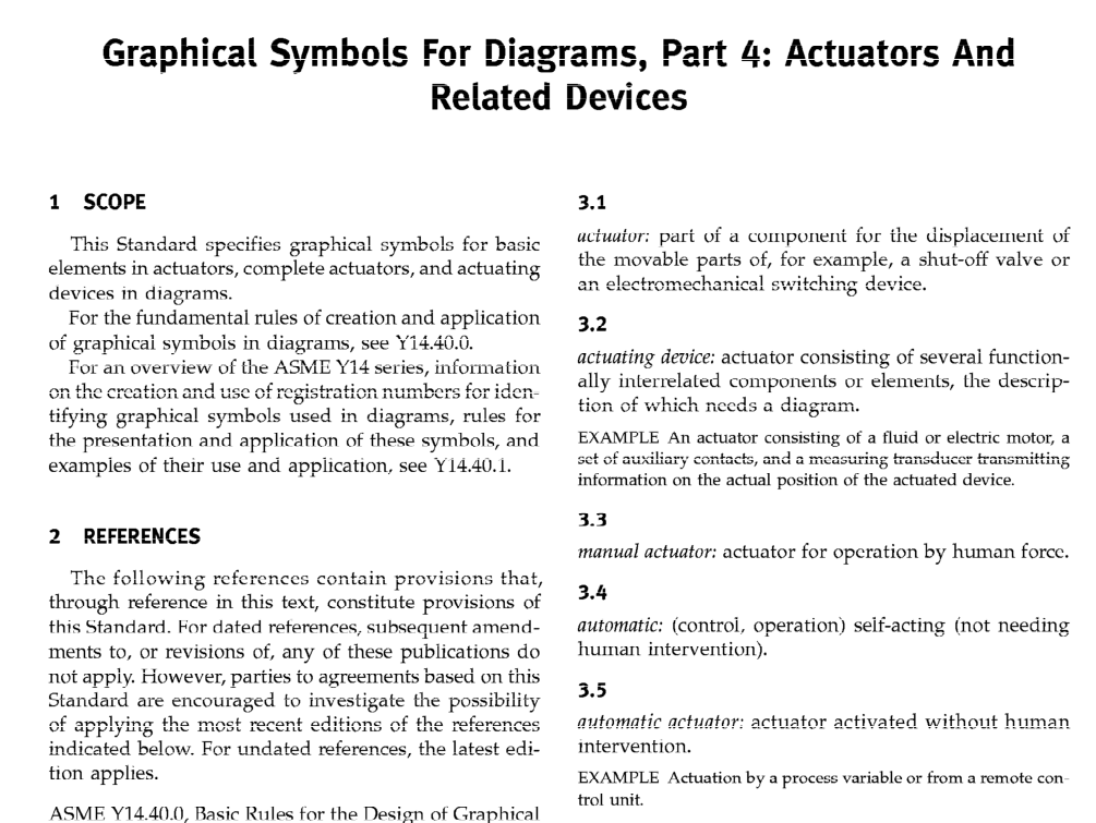
ASME Y14.40.4 pdf download GRAPHICAL SYMBOLSFOR DIAGRAMS, PART 4: ACTUATORS ANDRELATED DEVICES
sCOPE
This Standard specifics graphical symbola for basicelements in actuators, complete actuators, and actuatingdevices in diagrams.
For the fundamental rules of creation and applicationof graphicai symbois in diagrams, see Y14.40.0.
For an overview of the ASME Y14 series,informationon the creation and use of registration numbers for iden-tifying graphical symbols used in diagrams,rules forthe presenfation and application of these symbols, andexamples of their use and application, see Y14.40.1.
2REFERENCES
Thc following rcfcrcnccs contain provisions that,through reference in this text,constitute provisions ofthis Standard. For dated references, subsequent amend-ments to, or revisions of, any of these publications donot apply. However, parties to agreements based on thisStandard are encouraged to investigate the possibilityof applying the most recent editions of the referencesindicated below.For undated references,the latest edi-tion applies.
ASME Y14.40.0, Basic Rules for the Design of GraphicalSymbols for Use in the Technical Documentation ofProducts
ASME Y14.40.1,Gtapltical Syubols for Diagrams,Part1:General Information and Indexes
ASME Y14.40.2,Graphical Symbols for Diagrams,Pert2: Symbols Having General Application
ASME Y14.40.7,Graphical Symbols for Diagrams,Part7: Basic Mechanical Components
ASME Y14.40.8, Graphical Symbols for Diagrams.Part8: Vaives and Dampers
Publisher:The American Society of Mechanical Fngi-neers (ASME International),Three Park Avenue, NewYork, iNY 10016; Order Department: 22 Law Drive,P.O. Box 2300,Fairfield, NJ07o07
3TERMS AND DEFINITIONS
For the purposes of this Standard, the following termsand definitions apply.
3.1
actuator: part of a component for the displacement ofthe movable parts of, for example, a shut-off valve oran electromechanical switching device.
3.2
actuating device: actuator consisting of several function-ally inlerrelaled components or elements,the descrip-tion of which nccds a diagram.
EXAMPLE An actuator consisting of a fluid or electric motor, asct of auxiliary contacts, and a measuring transducer transmittinginformation on the actual position of the actuated device.
3.3
mzanual actuator: actuator for opcration by human force.
3.4
autonatic: (control,operation) self-acting (not needinghunan intervention).
3.5
automatic acfuator: actuator activated without humanintervention.
EXAMPLE Actuation by a proccss variable or from a remote control unit.
3.6
automatic return device: device for returning movableparts, for example, those of a valve, to initial position (at-rest position) after an actuating force has been removed.
3.7
clutch: device for connecting and disconnecting workingparts, for example, of a machine.
3.8
deluy device: device providing a tine interval betweenthe instant when an actuating force is applied orremoved and the instant when the consequent changeof position or state of the affected parts sfarts.
3.9
detent: device that retains movable parts,for example,those of a valve, in a certain position until sufficientforce is applied to overcome the detaining force in orderto move the parts to another position.
