ASME NTB-2 pdf download
ASME NTB-2 pdf download Background Information for Addressing Adequacy or Optimization of ASME BPVC Section III, Division 5 Rules for Metallic Components
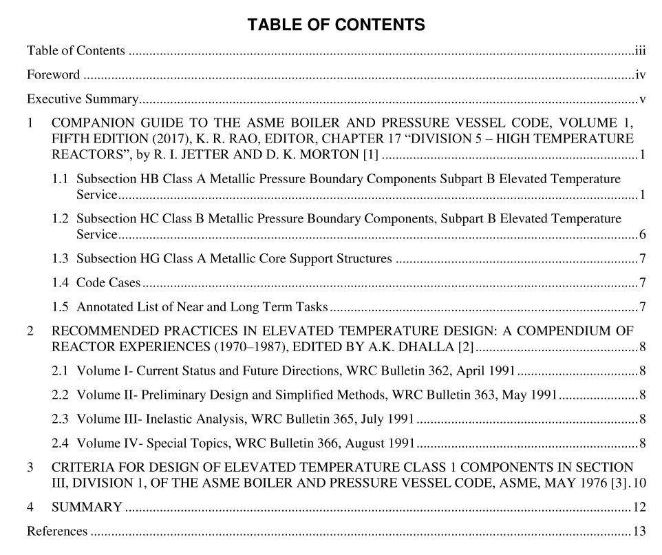
1.3Subsection HG Class A Metallic Core Support Structures
Section 17.4.4.10 provides a brief overview ofhow the core support rules relate to the Subsection NG ruleswhen creep effects are negligible and to the HBB rules in BPVC Section Ill, Division 5 when they are nott discusses the differences for core support structures and pressure retaining structures with respect t(bolting (higher allowable stresses) and testing and overpressure protection (not required). The rules forBPVC Section Il,Division 5 core support structures below the creep repime are in Appendix HGB-Il. Theelevated temperature rules when creep is significant are in HGB-1000 to HGB-8000. The guidance forwhen creep is negligible is in Appendix HGB-IV.
1.4 Code Cases
N-290-1, Expansion Joints in Class 1, Liquid Metal Piping, Section IIl, Division 1Section 17.4.4.1l.1 describes the incentive for the use of bellows, the issues addressed, and how they wereresolved, including the more significant features. (Note: As the title of the Code Case indicates, it has notbeen updated in some time and needs to reflect the establishment of BPVC Section Ill, Division 5 for hightemperature reactor components.)
N-812-1, Alternate Creep-Fatigue Damage Envelope for 9Cr-1Mo-V Steel, Section IIl, Division 5Section 17.4.4.11.2 explains the justification and limitations for the use of a less conservative interactionintercept point (0.3, 0.3) on the creep-fatigue damage diagram for 9Cr-1Mo-V steel. Note: The referenceto an intercept of (0.1, 0.10) should be (0.1, 0.01) for the unmodified damage diagram]
N-861, Satisfaction of Strain limits for Division 5, Class A Components at Elevated TemperatureService Using Elastic-Perfectly Plastic Analysis; and N-862, Calculation of Creep-Fatigue forDivision 5, Class A Components at Elevated Temperature Service Using Elastic-Perfectly PlasticAnalysis
The discussion in Section 17.4.4.11.3 explains the rationale, advantages, and supporting information forthe application of an Elastic-Perfectly Plastic (“EPP”) based analysis methodology for the evaluation ofstrain limit and creep-fatigue damage. Also of note is a revised. less conservative consideration of Level Cevents.
1.5Annotated List of Near and Long Term TasksTable 17.10 on the last page of Chapter 17 is an overview of near and long term goals for elevatedtemperature metallic components that was developed from a series of whitepapers and roadmaps fromseveral years ago. It has been used for tracking various code development projects since. Generally, it is ingood agreement with current accomplishments and ongoing activities.
2 RECOMMENDED PRACTICES IN ELEVATED TEMPERATURE DESIGN: A COMPENDIUM OF REACTOR EXPERIENCES (1970–1987), EDITED BY A.K. DHALLA [2]
As indicated by the title, this is a four-volume compendium of experience and lessons learned in the application of elevated structural design methods to sodium cooled fast breeder reactor components. Each volume has multiple individually-authored chapters. In addition to inputs from U.S. authors, there was significant input from Germany, France and Japan. All of the chapters are of general interest, but the main focus is not on the background for the design rules themselves, however, there are a number of chapters that will be highlighted for their influence on design rule development. Note that the chapters are numbered sequentially, chapter numbers in the next volume pick up where the chapter numbers in the preceding volume left off.
