IEC 61280-1-3 pdf download
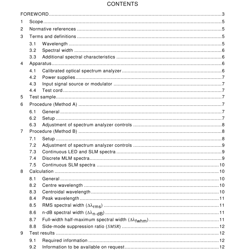
IEC 61280-1-3 pdf download Fibre optic communication subsystem test procedures – Part 1-3: General communication subsystems – Central wavelength and spectral width measurement
4 Apparatus
4.1 Calibrated optical spectrum analyzer This special-purpose test equipment uses a dispersive spectrophotometric method to resolve and record the optical spectral distribution. The required wavelength resolution and range depends on the type and variety of signals to be measured. Generally, LED sources have wide spectra with little structure so a range of at least 200 nm and resolution of 1 nm or narrower are recommended. Laser sources have much narrower spectra and may be used in wavelength-domain multiplexing (WDM) applications, where more accurate determination of the wavelength is required. A wavelength resolution of 0,1 nm or narrower is recommended and the actual requirement is determined by the application. In any case, the sensitivity and wavelength range of the spectrum analyzer shall be sufficient to measure all of the spectrum within at least –20 dB from the peak power. For measurement of SMSR, a larger dynamic range is typically required.
OSA equipment shall be calibrated in accordance with IEC 621 29. The equipment used shall have a valid calibration certificate in accordance with the applicable quality system for the period over which the testing is done.
4.2 Power supplies
As required for the device under test.
4.3 Input signal source or modulator
The input signal source is a signal generator or modulator with the appropriate digital or analogue signal of the system.
4.4 Test cord
Unless otherwise specified, the physical and optical properties of the test cords shall match to the cable plant with which the equipment is intended to operate. The cords shall be 2 m to 5 m long, and shall contain fibres with coatings which remove cladding light. Appropriate connectors shall be used. Single-mode cords shall be deployed with two 90 mm diameter loops or otherwise assure rejection of cladding modes. If the equipment is intended for multimode operation and the intended cable plant is unknown, the fibre size shall be 50/1 25 µm.
5 Test sample
The test sample shall be a specified fibre optic subsystem, transmitter, or light source. The system inputs and outputs shall be those normally seen by the user. The spectral width parameters are typically used for characterizing MLM and LED transmitters. The width of MTM and SLM lasers without modulation are normally too narrow to measure with the dispersive spectral instruments used with this method. Modulated SLM transmitters have broadened linewidths for high data rates (above about 2,5 Gb/s) and due to chirp that may be measurable by this method.
