IEC 61921 pdf download
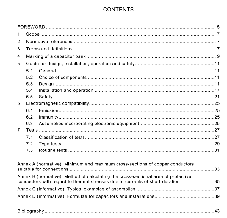
IEC 61921 pdf download Power capacitors – Low-voltage power factor correction banks
1 Scope
This International Standard is applicable to low-voltage a.c. capacitor banks intended to beused for power factor correction purposes, equipped with a built-in switchgear and controlgearapparatus capable of connecting to or disconnecting from the mains part(s) of the bank withthe aim to correct its power factor.
Low-voltage power factor correction banks if not otherwise indicated hereinafter and whereapplicable shall comply with the requirements of lEC 60439-1 and those of lEC 60439-3.
2Normative references
The following referenced documents are indispensable for the application of this document.For dated references, only the edition cited applies.For undated references, the latest editionof the referenced document (including any amendments) applies.
IEC 60439-1:1999,Low-voltage switchgear and controlgear assemblies – Part 1: Type-testedand partially type-tested assemblies
IEC 60439-3:1990,Low-voltage switchgear and controlgear assemblies – Part 3: Particularrequirements for low-voltage switchgear and controlgear assemblies intended to be installedin places where unskilled persons have access for their use – Distribution boards
IEC 60831-1:1996,Shunt power capacitors of the self-healing type for a.c. systems havinga rated voltage up to and including 1 000 v – Part 1: General – Performance,testing andrating -Safety requirements – Guide for installation and operation
IEC 60931-1:1996,Shunt power capacitors of the non-self-healing type for a.c. systemshaving a rated voltage up to and inciuding 1 000 v – Part 1: General – Performance, testingand rating -Safety requirements – Guide for installation and operation
3 Terms and definitions
For the purpose of this document,the following definitions, together with the definitions foundin lEC 60439-1,IEC 60831-1 andlEC 60931-1 apply.
3.1
low-voltage a.c. capacitor bank
combination of one or more low-voltage capacitor units together with associated switchingdevices and control,measuring,signalling,protective, regulating equipment,etc., completelyassembled under the responsibility of the manufacturer with all the internal electrical andmechanical interconnections and structural parts
3.2
step of capacitor bankstep
combination of one or more capacitor units switched together
3.3
automatic reactive power regulatorcontroller
circuit designed to calculate the reactive power absorbed by the load connected to the powerline and to control the switching on and off of the steps of the automatic bank, in order tocompensate for the reactive power
NOTE 1 The reactive power is normally calculated at the fundamental frequency.
NOTE 2 The controller may be “built-in”or “free-standing” and has usually to be adjusted for each bank beforeoperation.
3.4
transient inrush current It
transient overcurrent of high amplitude and frequency that may occur when a capacitor isswitched on, the amplitude and frequency being determined by factors such as the short-circuit impedance of the supply, the amount of energized capacitance switched in parallel andthe instant of the switching
3.5
rated reactive power on (of an assembly)
total reactive power of an assembly at the rated frequency and voltage,calculated by the totalimpedance of the bank including reactors, if any
4Marking of a capacitor bank
The following minimum information shall be given by the manufacturer in an instruction sheetor alternatively, on request of the purchaser, on a rating plate to be fixed on the assembly.
