IEC 60749-20 pdf download
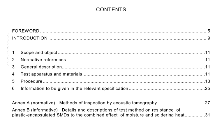
IEC 60749-20 pdf download SEMICONDUCTOR DEVICES – MECHANICAL AND CLIMATIC TEST METHODS – Part 20: Resistance of plastic-encapsulated SMDs to the combined effect of moisture and soldering heat
1 scope and object
This part of lEC 60749 applies to semiconductor devices (discrete devices and integratedcircuits).
This test method provides a means of assessing the resistance to soldering heat of plastic-encapsulated surface mount devices (SMDs).This test is destructive.
NOTE This test is identical to the test method contained in 2.3 of chapter 2 of IEC 60749 (1996), amendment 2,apart from the addition of this clause and clause 2 and the subsequent renumbering.
2Normative references
The following referenced documents are indispensable for the application of this document.For dated references, only the edition cited applies. For undated references, the latest editionof the referenced document (including any amendments) applies.
IEC 60068-2-20:1979,Environmental testing – Part 2: Tests – Test T: Soldering
IEC 60749-3,Semiconductor devices – Mechanical and climatic test methods – Part 3:External visual inspection
3General description
Package cracking and electrical failure in plastic-encapsulated SMDs can result whensoldering heat raises the vapour pressure of moisture which has been absorbed into SMDsduring storage.These problems are assessed. In this test method,SMDs are evaluated forheat resistance after being soaked in an environment which simulates moisture beingabsorbed while under storage in a warehouse or dry pack.
4Test apparatus and materials
a) Humidity chamber
The humidity chamber shall provide an environment complying with the temperature andrelative humidity defined in item c) of clause 5.
b)Reflow soldering apparatus
The infra-red convection, the convection and the vapour-phase reflow soldering apparatusshall provide temperature profiles complying with the conditions of soldering heat definedin items d)1) and d)2) of clause 5.The settings of the reflow soldering apparatus shall beadjusted by temperature profiling of the top surface of the specimen while it is undergoingthe soldering heat process,measured as shown in figure 1.
c) Holder
Unless otherwise detailed in the relevant specification, any board material, such as epoxyfibreglass or polyimide,may be used for the holder.The specimen shall be placed on theholder by the usual means and in a position as shown in figure 1. lf the position of thespecimen,as shown in figure 1,necessitates changing the shape of terminations andresults in subsequent electrical measurement anomalies,a position that avoids changingthe shape of terminations may be chosen,and this shall be specified in the relevantspecification.
d) wave-soldering apparatus
The wave-soldering apparatus shall comply with conditions given in item d)3) of clause 5.Molten solder shall usually be flowed.
e) Solvent for vapour-phase reflow soldering
Perfluorocarbon (perfluoroisobutylene) shall be used.
f)Flux
Unless otherwise detailed in the relevant specification,the flux shall consist of 25 % byweight of colophony in 75 % by weight of isopropyl alcohol, both as specified in appendix cof EC 6o068-2-20.
g) Solder
Solder of composition as specified in appendix B of lEC 60068-2-20 shall be used.
